Quick Answer: Where Should Flowmeters Be Installed in an MBR Plant?
Flowmeters in an MBR water reclamation plant are commonly considered at the plant influent, membrane permeate outlet and waste activated sludge line.
Depending on the process layout and control objectives, additional measurement points may include the equalization tank outlet, biological feed, mixed-liquor recycle, membrane-scouring air and, in sidestream systems, the external membrane circulation loop. Backwash flow should also be identified separately whenever permeate is used for backwashing. The final instrument list should follow the plant P&ID, process control strategy and water-balance requirements.
These are measurement-planning points rather than a universal meter count. Each measurement point should have a clearly defined process purpose.
Understanding the MBR Process Before Mapping Measurement Points
A membrane bioreactor (MBR) combines biological wastewater treatment with membrane separation.
Microorganisms break down organic pollutants in the biological treatment stage, while membranes separate treated water from suspended solids and biomass.
A typical MBR treatment sequence includes:
Influent → Pretreatment → Equalization → Biological Treatment → Membrane Separation → Permeate → Reclaimed Water
The actual arrangement depends on the plant design.
Submerged MBR Configuration
In a submerged MBR system, membrane modules are installed directly inside a biological treatment tank or a separate membrane tank.
Permeate is drawn through the membrane and collected for further treatment, reuse or discharge.
Many submerged systems also introduce air beneath the membrane modules to create movement along the membrane surfaces and help control solids accumulation.
Important measurement points may include:
Biological process feed.
Mixed-liquor recycle.
Membrane permeate.
Waste activated sludge.
Membrane-scouring air.
Backwash flow, where applicable.
Sidestream MBR Configuration
In a sidestream MBR system, mixed liquor is pumped from the biological treatment stage through external membrane modules before returning to the treatment process.
This arrangement introduces an additional circulation loop.
Engineers may need to monitor:
Membrane feed flow.
Membrane circulation flow.
Return flow to the biological treatment stage.
Permeate production.
The key difference is that sidestream systems have an external membrane circulation loop, while submerged systems have a different membrane and piping arrangement.
The flow measurement plan should therefore be developed from the actual process configuration rather than copied from another MBR project.
Key Flow Measurement Points in an MBR Water Reclamation Plant
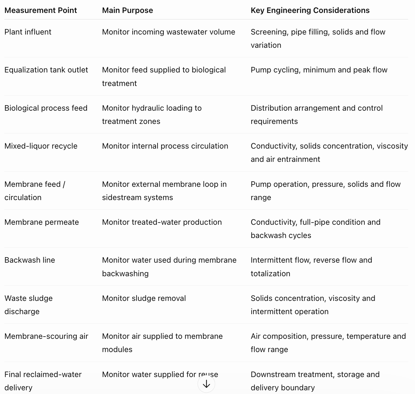
The following table provides a practical reference for identifying measurement locations during instrumentation planning.
Measurement Point | Main Purpose | Key Engineering Considerations |
|---|---|---|
Plant influent | Monitor incoming wastewater volume | Screening, pipe filling, solids and flow variation |
Equalization tank outlet | Monitor feed supplied to biological treatment | Pump cycling, minimum and peak flow |
Biological process feed | Monitor hydraulic loading to treatment zones | Distribution arrangement and control requirements |
Mixed-liquor recycle | Monitor internal process circulation | Conductivity, solids concentration, viscosity and air entrainment |
Membrane feed / circulation | Monitor external membrane loop in sidestream systems | Pump operation, pressure, solids and flow range |
Membrane permeate | Monitor treated-water production | Conductivity, full-pipe condition and backwash cycles |
Backwash line | Monitor water used during membrane backwashing | Intermittent flow, reverse flow and totalization |
Waste sludge discharge | Monitor sludge removal | Solids concentration, viscosity and intermittent operation |
Membrane-scouring air | Monitor air supplied to membrane modules | Air composition, pressure, temperature and flow range |
Final reclaimed-water delivery | Monitor water supplied for reuse | Downstream treatment, storage and delivery boundary |
View original table image: MBR plant flow measurement points
Let's examine the main measurement locations in more detail.
Plant Influent Measurement
The influent measurement point establishes the incoming hydraulic load of the treatment facility.
It is generally located at a defined incoming wastewater boundary, with the installation position selected according to screening, equalization and pipeline arrangements.
This measurement helps operators understand:
Total wastewater entering the plant.
Changes in incoming flow throughout the day.
Hydraulic loading during peak-flow periods.
Differences between incoming wastewater and downstream treatment feed.
Flowmeter selection consideration:
An Electromagnetic Flowmeter may be suitable for conductive wastewater applications.
However, engineers should confirm:
Liquid conductivity.
Suspended-solids concentration.
Minimum, normal and maximum flow.
Pipe filling conditions.
Liner and electrode compatibility.
Installation position and grounding.
If the influent is measured in an open channel rather than a full pipeline, the measurement arrangement should be reviewed separately. An appropriate Ultrasonic Flowmeter configuration may be considered where the channel and installation conditions permit.
Equalization Tank Outlet and Biological Process Feed
The equalization tank balances variations in incoming wastewater before it enters the biological treatment stage.
Consequently, the flow leaving the equalization tank may differ from the instantaneous plant influent flow.
Measuring this point separately can help operators understand the actual feed rate supplied to the biological process.
Important considerations include:
Minimum, normal and maximum feed flow.
Pump start-stop cycles.
Changes caused by tank-level control.
Short-duration flow peaks.
Potential air accumulation in downstream piping.
The influent and biological feed are different measurement boundaries. Whether both require separate meters depends on the plant's control and reporting requirements.
Mixed-Liquor Recycle Measurement
Some MBR configurations include internal circulation between biological treatment zones, such as anoxic and aerobic sections.
This circulation helps maintain the intended treatment process and biological operating conditions.
A flowmeter on the recycle line can help operators monitor the actual circulation rate and compare it with the required process flow ratio.
However, mixed liquor contains suspended biomass and other solids.
Before selecting a flowmeter, engineers should check:
Mixed-liquor conductivity.
Suspended-solids concentration.
Minimum and maximum recycle flow.
Pipe diameter and operating velocity.
Potential air entrainment.
Electrode and liner material compatibility.
An Electromagnetic Flowmeter may be considered when the liquid conductivity and installation conditions meet the instrument requirements.
Membrane Feed and Circulation Measurement
The membrane section is another important measurement area.
However, its flow arrangement depends on the MBR configuration.
In a submerged MBR system, membrane modules are installed inside the treatment tank. The main measurement focus may be permeate production and membrane-scouring air.
In a sidestream MBR system, mixed liquor is pumped through external membrane modules and returned to the process. The circulation loop becomes an additional measurement boundary.
Before selecting a meter, engineers should identify:
Actual membrane configuration.
Feed and return pipeline arrangement.
Pump operating conditions.
Minimum, normal and maximum flow.
Operating pressure.
Suspended-solids characteristics.
The purpose of the measurement should also be defined: process control, circulation monitoring, totalization or operational reporting.
Membrane Permeate Flow Measurement
Permeate is the treated water that passes through the membrane separation stage.
This is one of the most important measurement points in an MBR plant because it represents water produced by the membrane process.
Permeate measurement supports:
Monitoring treated-water production.
Calculating membrane flux when the active membrane area is known.
Recording total permeate volume.
Comparing production between membrane trains.
Evaluating changes in membrane operation.
Membrane flux is the permeate flow rate divided by the active membrane surface area.
One important distinction is the difference between gross permeate production and net reclaimed-water delivery.
Some MBR systems use permeate for membrane backwashing. If this water is returned to the membrane process, it should be accounted for separately when calculating the actual volume available for reuse.
Flowmeter selection consideration:
An Electromagnetic Flowmeter may be considered when permeate conductivity meets the meter's operating requirements.
An Ultrasonic Flowmeter may also be evaluated for suitable closed-pipe water lines, depending on pipe material, wall thickness, lining and installation conditions.
For Velomac's published Electromagnetic Flowmeter specifications, the minimum conductivity is ≥5 μS/cm. Actual permeate conductivity should therefore be verified before selecting the instrument.
Membrane Backwash Flow Measurement
Backwashing is an important operating stage in many membrane systems.
During backwashing, water may flow in the reverse direction through the membrane to remove accumulated material from the membrane surface.
Some systems use permeate as the backwash water source.
From a measurement perspective, this creates an important distinction:
Gross permeate production.
Permeate diverted for backwashing.
Net reclaimed water available for delivery.
If the backwash line has a separate measurement point, its flow and total volume can be recorded independently.
If the same pipeline and meter are used for forward permeate flow and reverse backwash flow, engineers should confirm that the selected instrument and PLC totalization logic can distinguish the required flow directions and operating cycles.
Ignoring backwash consumption can overstate the volume of reclaimed water available for external use.
Waste Sludge Flow Measurement
Sludge wasting is an important part of biological process management.
Excess sludge is periodically removed from the system to maintain the required biological solids inventory.
Measuring waste sludge flow helps operators monitor the volume removed from the treatment process.
However, sludge flow rate alone does not determine the amount of solids removed.
Engineers should consider both:
Waste sludge flow rate.
Total suspended-solids concentration.
These two values provide a better basis for calculating the mass of solids leaving the system.
Flowmeter selection consideration:
An Electromagnetic Flowmeter may be considered for conductive sludge applications.
The selection should account for solids concentration, viscosity, intermittent pumping, minimum operating flow and potential deposits on measuring electrodes.
Membrane-Scouring Air Measurement
Air is an important operating medium in many submerged MBR systems.
Air supplied beneath the membrane modules creates movement along the membrane surfaces, helping control solids accumulation and maintain the intended membrane operating conditions.
Monitoring the air supply can help operators understand air distribution between membrane tanks or individual treatment trains.
Typical measurement objectives include:
Monitoring total blower air supply.
Comparing air distribution between membrane trains.
Identifying changes in air consumption.
Supporting blower operation and process monitoring.
Flowmeter selection consideration:
A Thermal Mass Flowmeter may be considered for suitable membrane-scouring air applications.
Before selection, confirm:
Minimum, normal and maximum air flow.
Operating pressure.
Air temperature.
Humidity and potential condensate.
Pipe diameter.
Required reference conditions for reported gas volume.
Installation position and straight-pipe requirements.
The measurement location should also reflect whether the plant needs total blower air consumption or individual train-level monitoring.
Final Reclaimed-Water Delivery
The membrane permeate outlet and the final reclaimed-water delivery point may represent different measurement boundaries.
For example, water may pass through additional treatment, disinfection, storage or distribution stages after membrane separation.
If the plant needs to report the actual water supplied to industrial or irrigation customers, a separate delivery measurement point may be appropriate.
Engineers should distinguish:
Gross membrane permeate production.
Water consumed internally.
Water entering storage.
Water delivered to the reuse network.
This distinction helps the plant establish a clearer water balance and report actual reclaimed-water delivery.
Separate Internal Circulation from External Plant Flow
One important consideration when designing an MBR flow measurement system is the distinction between external and internal flows.
These values serve different purposes and should be recorded according to clearly defined measurement boundaries.
External plant flows may include:
Incoming wastewater.
Final treated-water delivery.
Waste sludge discharge.
Bypass or overflow, where applicable.
External makeup and cleaning water, where included in the water balance.
Internal process flows may include:
Mixed-liquor recycle.
Membrane circulation.
Permeate used for backwashing.
Internal cleaning and return streams.
Utility flows may include:
Membrane-scouring air.
Cleaning-related water and chemical streams.
For example, a plant may produce a certain volume of gross membrane permeate while using part of that water for backwashing.
If both values are treated as external water production, the plant's net reclaimed-water volume will be overstated.
The same principle applies to internal recycle. Recirculated water should be distinguished from new incoming wastewater when calculating plant water balances.
A clear measurement boundary should define what enters, what leaves, what is recycled and what is consumed internally.
How to Select Flowmeters for Different MBR Measurement Points
MBR plants handle several different liquid and gas streams. Flowmeter selection should therefore be based on the actual process conditions at each measurement point.
The following Velomac products may be considered where their operating requirements are met.
Electromagnetic Flowmeter
Potential applications include:
Screened influent wastewater.
Biological process feed.
Conductive mixed liquor.
Internal recycle lines.
Suitable permeate lines.
Waste sludge transfer.
An Electromagnetic Flowmeter is designed for conductive liquid measurement.
Key selection checks include:
Liquid conductivity.
Suspended-solids concentration.
Minimum, normal and maximum flow.
Full-pipe condition.
Pipe diameter and operating velocity.
Liner material.
Electrode material.
Grounding and installation conditions.
For low-conductivity permeate, verify the actual conductivity before selecting an Electromagnetic Flowmeter.
Ultrasonic Flowmeter
An Ultrasonic Flowmeter may be evaluated for suitable water and process-liquid measurement applications.
Depending on the configuration, it may be considered for:
Closed-pipe treated-water lines.
Existing water pipelines where clamp-on installation is appropriate.
Suitable open-channel measurement applications.
For clamp-on applications, engineers should confirm:
Pipe material.
Pipe outside diameter.
Wall thickness.
Internal lining.
Pipe condition.
Available straight-pipe length.
Sensor mounting access.
Required signal output.
The existing pipe construction and installation conditions must be reviewed before choosing an ultrasonic configuration.
Thermal Mass Flowmeter
A Thermal Mass Flowmeter may be considered for membrane-scouring air and other suitable gas measurement applications.
It measures gas mass flow directly, with configuration depending on the gas and operating conditions.
Key selection checks include:
Gas type and composition.
Minimum, normal and maximum flow.
Operating pressure.
Operating temperature.
Humidity and moisture conditions.
Pipe diameter.
Installation arrangement.
Required reference conditions.
The same flowmeter technology should not automatically be applied to every measurement point in an MBR plant. Each line requires its own application review.
What Information Should Engineers Prepare Before Flowmeter Selection?
Before requesting a quotation or specifying flowmeters for an MBR project, engineers should prepare the operating information for each individual measurement point.
Process Information
Measurement point and instrument tag number.
MBR configuration: submerged or sidestream.
Medium being measured.
Process function.
Whether the flow is continuous or intermittent.
Whether the line carries recycle, permeate, sludge, backwash or air.
Operating Conditions
Minimum flow rate.
Normal flow rate.
Maximum flow rate.
Short-duration peak flow, where applicable.
Operating pressure.
Operating temperature.
Conductivity and suspended-solids concentration for liquid applications.
Gas composition and reference conditions for air measurement.
Minimum, normal and maximum flow should be confirmed before discussing meter size or turndown.
Pipe Information
Nominal pipe diameter.
Pipe material.
Internal lining, if applicable.
Pipe wall thickness for ultrasonic applications.
Flange standard and pressure rating.
Installation orientation.
Available straight-pipe length.
Distance from pumps, valves and elbows.
Whether the pipe remains completely full.
Instrument Requirements
Required measurement accuracy.
Power supply.
Output signal.
PLC/DCS or other control-system connection.
Local display or remote monitoring.
Communication protocol.
Enclosure protection.
Material and environmental requirements.
Required calibration and inspection documents.
Procurement Information
Instrument quantity and tag list.
Approved datasheets and drawings.
Required certificates.
FAT or inspection requirements, if applicable.
Required delivery schedule.
Export packaging requirements.
Shipping destination.
Agreed delivery term and transport scope.
Preparing these details early helps engineering and procurement teams review the application and quotation on the same technical basis.
What Should EPCs Check Before Ordering and Shipping MBR Flowmeters?
Selecting the correct flowmeter is only one part of an MBR instrumentation package.
For overseas water treatment projects, documentation, factory inspection, export packaging and delivery arrangements should also be reviewed before shipment.
Confirm the Instrument Configuration Before Production
Before manufacturing starts, EPCs and procurement teams should verify that the approved instrument configuration matches the project requirements.
Important details include:
Instrument tag number and measurement location.
Approved model and nominal pipe size.
Flange standard and pressure rating.
Wetted-part and housing materials.
Operating pressure and temperature.
Minimum, normal and maximum flow rates.
Power supply and output signals.
Enclosure protection and required certifications.
Accessories and installation requirements.
For MBR projects, each measurement point should have its own approved specification.
Influent, mixed-liquor recycle, permeate, sludge and membrane-scouring air should be reviewed as separate instrument applications.
It is also worth confirming the supply scope for mating flanges, bolts, gaskets, cables and other accessories before production.
What Calibration and Inspection Documents Should Be Prepared?
For project-based procurement, buyers should agree on the required inspection and documentation package before production.
Depending on the contract and project specifications, this may include:
Approved technical datasheet.
General arrangement drawing.
Wiring diagram.
English operating manual.
Factory calibration certificate.
Material Test Report (MTR), where specified.
Factory inspection or FAT records, where required.
Product identification and serial-number records.
Packing list and shipment identification.
One important check is document traceability.
The instrument model, serial number and tag identification should correspond to the actual equipment being supplied.
A calibration certificate should be traceable to the specific instrument rather than presented as an unrelated generic document.
Buyers should also review the agreed calibration scope, including the test medium, test points, method and reported results where applicable.
Calibration evidence and application suitability are two separate checks. A calibrated meter still needs to be selected for the correct medium, operating range and installation conditions.
How Should Flowmeters Be Protected During Sea Freight?
Industrial flowmeters may pass through several stages of handling before reaching the installation site.
Long-distance sea freight and subsequent storage introduce considerations such as:
Humidity and condensation.
Mechanical vibration.
Handling impact.
Stacking and loading forces.
Extended storage before installation.
Packaging should therefore be matched to the instrument type, dimensions, weight, transportation route and expected storage conditions.
Important protection measures include:
Flange and Connection Protection
Use suitable end covers to protect flange faces and keep foreign materials out of the flow passage.
Measuring Component Protection
For Electromagnetic Flowmeters, take care to protect the internal liner and electrode areas from impact, contamination and improper handling.
Electronics Protection
Protect the transmitter, display, terminal box and cable entries against moisture exposure during transportation and storage.
Moisture Protection
Use suitable moisture barriers and desiccants where required by the packaging design, transportation duration and storage conditions.
Mechanical Protection
Secure the instrument inside the crate to limit movement during freight handling. The packaging should support the instrument appropriately without placing loads on vulnerable components.
Accessory Identification
Pack and label cables, mounting parts and other accessories so they can be checked against the packing list during receiving inspection.
Packing Evidence
Where required, take photographs of the instrument condition, internal protection, accessories and completed crate before shipment.
For wooden export packaging, applicable destination-country treatment and marking requirements should also be confirmed.
Export packaging should be agreed before dispatch, rather than treated as an unspecified final packing step.
What Shipping Documents and Delivery Costs Should Buyers Confirm?
International procurement involves more than checking the physical instrument.
The equipment description and quantities should correspond across the commercial and shipping documents.
Depending on the shipment arrangement, buyers may need to review:
Commercial Invoice.
Packing List.
Applicable transport document.
Export documentation.
Equipment identification records.
Agreed inspection and calibration documents.
The quotation should also clearly define the delivery scope.
Before confirming the order, buyers should establish:
Whether export packaging is included.
Whether international freight is included.
Whether cargo insurance is included.
Which Incoterms rule applies.
Which party handles export clearance.
Which party handles import clearance.
Whether import duties and destination charges are included.
Whether local delivery to the project site is included.
The instrument price and the total landed cost are different figures.
A clearly defined quotation scope helps EPCs and procurement teams compare supplier offers on the same basis and understand which costs remain outside the equipment quotation.
What Should Buyers Check When the Equipment Arrives?
Receiving inspection is an important step before instruments are released for installation.
The receiving team should check:
Package condition and any visible transportation damage.
Instrument quantity and model against the packing list.
Nameplate information, tag numbers and serial numbers.
Flange faces, housing, connectors and exposed components.
Calibration certificates and other agreed documents.
Accessories and installation materials included in the order.
Where damage or discrepancies are identified, record the affected package and instrument identification, retain photographs and notify the relevant supplier or logistics contact promptly in line with the agreed reporting and claim procedures.
Pre-shipment inspection and receiving inspection should form one continuous verification process.
Prepare for Installation and Technical Support Before Dispatch
The project team should also confirm what information will be available when the instruments reach the site.
Depending on the selected configuration and project requirements, this may include:
English operating manual.
Wiring diagram.
Installation instructions.
Configuration instructions or PC software, where applicable.
Signal and communication details.
Agreed spare parts and accessories.
Technical support contact.
This allows the installation and commissioning team to prepare before the equipment reaches the site.
For overseas EPC projects, it is worth confirming the document package and technical communication arrangements during procurement rather than waiting until commissioning.
Common Flow Measurement and Procurement Mistakes in MBR Projects
Several problems can be avoided during the design and procurement stages.
Mistake 1: Treating Every MBR Configuration as Identical
Submerged and sidestream systems have different process arrangements. Measurement points should follow the actual P&ID.
Mistake 2: Measuring Only the Plant Inlet and Final Outlet
These two measurements provide an overall picture but may leave internal circulation, sludge removal, membrane production and air consumption unclear.
Mistake 3: Combining Gross Permeate with Net Reclaimed-Water Delivery
Backwash and other internal water consumption should be accounted for separately when calculating the actual volume available for reuse.
Mistake 4: Selecting a Meter Using Nominal Flow Alone
The actual minimum, normal and maximum operating flow should be confirmed before discussing meter size and turndown.
Mistake 5: Assuming All Treated Water Is Suitable for Electromagnetic Measurement
Liquid conductivity must be checked against the selected meter's requirements.
Mistake 6: Calculating Sludge Removal from Flow Alone
Solids concentration should also be considered when evaluating the mass of sludge removed.
Mistake 7: Confirming Export Packaging Only at the Final Stage
Packaging, document requirements and shipping responsibilities should be agreed before dispatch.
Mistake 8: Checking the Certificate Without Checking the Instrument
The calibration record, instrument identification, nameplate and packing list should correspond to the actual equipment supplied.
Practical Checklist for MBR Flow Measurement Projects
Before finalizing the instrumentation plan and procurement package, engineers can use the following checklist.
Process and Measurement Boundaries
Identify the MBR configuration: submerged or sidestream.
Mark influent, biological feed and permeate measurement points on the P&ID.
Identify all internal mixed-liquor recycle lines.
Confirm membrane circulation measurement requirements.
Identify membrane-scouring air measurement requirements.
Define waste sludge measurement locations.
Separate internal process flows from external water-balance measurements.
Account for backwash and cleaning-related water consumption.
Flowmeter Selection
Confirm minimum, normal and maximum flow for every measurement point.
Verify conductivity, solids concentration and material compatibility.
Check pressure and temperature.
Confirm pipe diameter, material and internal lining.
Verify full-pipe conditions and installation position.
Check straight-pipe requirements and nearby disturbances.
Confirm required output signals and PLC/DCS integration.
Define forward and reverse flow measurement requirements where applicable.
Quality and Shipment
Confirm the approved datasheet and instrument configuration.
Agree on calibration and inspection document requirements.
Check instrument identification and certificate correspondence.
Confirm MTR and FAT requirements where specified.
Agree on export packaging and moisture protection.
Confirm accessories and packing list.
Define Incoterms, freight, insurance and destination responsibilities.
Establish receiving inspection and damage-reporting procedures.
Confirm English manuals and technical support arrangements.
Common Questions About MBR Flow Measurement
Q1. What are the main flow measurement points in an MBR water reclamation plant?
Commonly considered points include plant influent, biological process feed, mixed-liquor recycle, membrane permeate, waste sludge and membrane-scouring air. Sidestream systems may also require measurement around the external membrane circulation loop.
Q2. Does every MBR plant need a separate flowmeter at every point?
No. The required instrumentation depends on the MBR configuration, P&ID, process control strategy and water-balance requirements. Each measurement point should have a defined operational purpose.
Q3. Can an Electromagnetic Flowmeter measure MBR permeate?
Yes, provided the liquid conductivity meets the selected instrument's requirements. Velomac's published Electromagnetic Flowmeter specification lists a minimum conductivity of ≥5 μS/cm. Actual permeate conductivity should be verified before selection.
Q4. How can membrane-scouring air flow be measured?
A Thermal Mass Flowmeter may be considered for suitable air applications. Gas type, operating pressure, temperature, humidity, flow range and reference conditions should be confirmed before selection.
Q5. What should overseas buyers check before shipping MBR flowmeters?
Confirm the approved instrument configuration, calibration records, instrument identification, agreed inspection documents, export packaging, packing list, transport responsibilities and receiving inspection requirements before dispatch.
Review Your MBR Flow Measurement and Delivery Requirements
An MBR water reclamation plant involves multiple liquid and air streams, each with a different measurement purpose.
Identifying the correct measurement boundaries is the first step. Confirming the instrument configuration, calibration scope, documentation and transportation arrangements helps the project team prepare for procurement and installation.
Velomac Flow Meter provides manufacturer-direct application support and in-house calibration facilities.
For MBR projects, our team can review the medium, flow range, pipe conditions, material requirements, installation space, signal output and agreed inspection and shipment requirements before product selection.
Share your MBR P&ID, instrument list or individual measurement requirements with Velomac for an application review.